Get the outside diameter of the two pipes that are side by side. Make a close-to-scale model of your pipe configuration using that piece of copper wire.

Steel Frame Pipe Rack Tutorials Computers And Structures Inc Technical Knowledge Base
2x6m12m and overall length of HCR unit-114 pipe rack is 3330m North south rack2370m East- west Rack60m and fire heater connecting Rack 3 x 12m36m.
. The steel pipe rack design play an important role in the proper functioning of the power plants. The Pipe racks connect all the equipment with piping that cannot run through the equipment areas. Where consideration of uplift or system stability due to wind or seismic occurrences is required use 60 of the.
Pipe Rack Drawing for Oil Field. The spacing between pipe rack portals shall be taken as 6m in general. If there are any flanges use the outside diameter of the flanges.
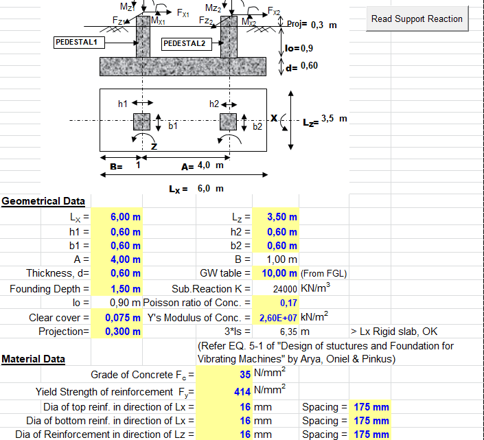
The tributary area is the tributary height times the tributary length of the cable tray. They may also be used to support mechanical equipment vessels and valve access platforms. Design Data Concrete Piers Size 15 ft x 15 ft Pile Cap Foundations f c 3000 psi f y 60000 psi Thickness 3 ft Clear Cover 2 in.
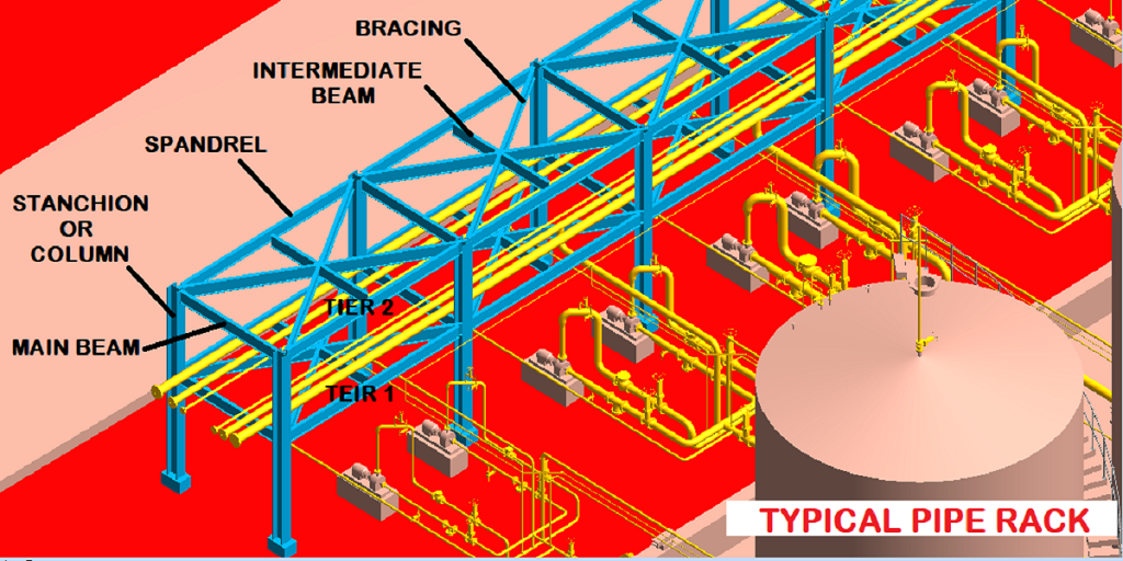
Their main function is to offer support to power cables instrument cable trays and pipes in general. Design of Structural Steel Pipe Rackspdf. It can give you a real feel for what you want to try to do with the real pipe.
Download View Design Calculation Report - Pipe Rack - And Foundation as PDF for free. Select the line with maximum temperature first. Use a mini- mum force coeffi cient of C f.
Pipe tiers elevation calculation. Made In The USA. Up to 10 cash back you will start with the absolute basics ie.
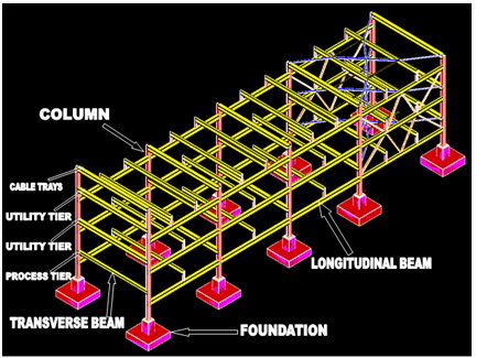
DRAKE and ROBERT J. WALTERABSTRACTPipe racks are structures in petrochemical chemical and power plants that are designed to support pipes power cables and instrument cabletrays. Select an elevation of pipe rack and check what are the lines running over that rack.
Concrete Piles f c 4000 psi f y 60000 psi Diameter 25 ft Clear Cover 3 in. Primary loads Eo and Ee are developed and used in separate load combinations to envelope the seismic design of the pipe rack. 19 rows During design of Pipe Rack certain points need to be taken into consideration for.
Geoff Barker IEngMEI in The Engineers Guide to Plant Layout and Piping Design for the Oil and Gas Industries 2018. 07 on pipes. The tributary height for each pipe level should be taken as the largest tray height plus 10 of the pipe rack trans- verse width.
Design calculation report - Pipe rack - and foundation. Call Us We Will Work To Build The Perfect Storage Solution For You. ATransverse Beams In computing the allowable bending stress Fb the unbraced length shall be taken as the span of the beam and the AISC factor Cb shall be used to account for end fixity.
The maximum segment for the pipe rack shall be limited to 42 m in length unless calculations indicate otherwise. Pipe racks are usually located in the. Push the ends together to see where the deflection goes and what bends the most.
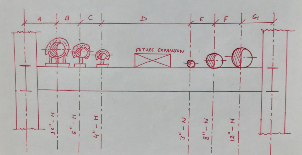
The width of the pipe rack is estimated as per below equation W f x n x s A B f Safety factor 15 if pipes are counted from the PFD 12 if pipes are counted from P ID. Foundation Loads Load Case Load kips P 1 P 2 P 3 P 4. Pipe Rack Design Philosophy.
This can be done by looking at our pipe datasheets for bare pipes or calculate it by using the method below. B SENORO GAS DEVELOPMENT PROJECT DATE. Pipe racks are the main highway in a process facility.
Design is in accordance with relevant American codes ASCE 7-05 for Design Loads AISC 360-05 for Design of Steel Elements ACI 318-05. Bend it into the shape of your pipe configuration and set it down on the desk. Width of the Pipe rack The width of the rack shall be 6 m 8 m or 10 m for single bay and 12 m 16 m or 20 m for double bay having 4 tiers maximum.
Design of Structural Steel Pipe RacksRICHARD M. The Pipe Rack is modeled and Designed in STAAD-Pro and SAFE design softwares. Calculate transverse wind on each cable tray level.
If there is insulation or a heat shield include this as part of the outside diameter. N Number of lines in the densest area upto the size of 18 Inch s 300mm estimated average spacing 225mm if lines are smaller than 10 Inch. Check the allowed maximum movement outside loop say 75mm and place the first anchor at a distance which will be nearer to the allowed thermal movement 75mm as mentioned above.
Design of Pipe Rack involves considerable planning and cor-ordination with other engineering groups. Calculating loads on the pipe racksyour trainer proceeds step by step through the process of modelling columns beams stringers bracingapplying dead loads product loads thermal loads wind loadsnext he proceeds further on how to assign the properties to the structural steel members assigning. This calculations dealt for HCR Hydrocracker Unit only The width of pipe rack 12m having three columns ie.
Pipe rack piping layout Accessways on pipe rack Cable tray arrangement Future Space Spacing between rack beams Pipe rack loading to civil. Rack Design involves following activities. Ad The Most Innovative Solution To Organizing Storing Your Sheet Metal Efficiently.
P W - s x p x d s Spacing of pipe rack bent p pipe weight considered kPa d pipe diameter W pipe concentrated load. Pipe rack width calculation. Four different Pipe racks are modeled LRFD Design philosophy is followed for analysis and Design of various Elements of Pipe rack.
ASCE Guidelines for Seismic Evaluation and Design of Petrochemical Facilities 1997 also provides further guidance and information on seismic design of pipe racks. Live Load in operating or maintenance platform are 250 kNm2 Live Load 25 x 3 75 kNm --- span 3 m Page 7 of 15 f CALCULATION OF PIPE RACK STRUCTURE Doc. Sometimes the pipe racks can also be used for offering support to mechanical equipments and vessels apart from valve access platforms.
AAM ENGG CERT MAG SAS SAUDI ARABIAN OIL COMPANY JO -21-00052-0001 Structural Calculation Metering Building B 0F1 REV NO. However it can be increased to 8m depending on the size of the pumps to be housed below the pipe rack. 121 Pipe racksWidths Bent Spacings and Elevations of Racks.
Length 33 ft Pile embedment 6 in.

Calculation Of Pipe Rack Weight Spreadsheet
Pipe Rack Design And Calculations Make Piping Easy
Pipe Rack And Pipe Track Design And Engineering
Pipe Rack Design And Calculations Make Piping Easy
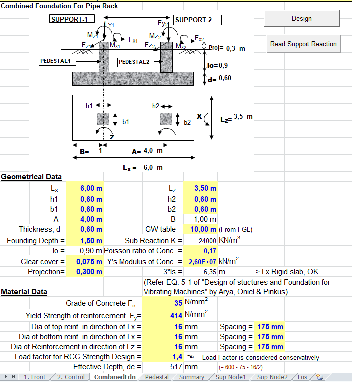
Combined Foundation For Pipe Rack Spreadsheet
Combined Foundation For Pipe Rack Spreadsheet

Steel Frame Pipe Rack Tutorials Computers And Structures Inc Technical Knowledge Base

Design Of Pipe Rack Layout Considerations
0 comments
Post a Comment